Setting Up Cull Operations to Get Only Needed Points
Now that we’ve created our grids and established the main site geometry, we’re ready to start building our column grid system.
In this step, we’ll generate grid intersection points, move them up to each level, and then filter out only the points that fall within our building massing. This gives us a clean, data-driven foundation for our structural layout.
Creating Grid Intersections
We’ll start by using our existing horizontal and vertical grid lines to find their intersection points.
-
Go back to the curves that represent your grid lines in Grasshopper.
These are the same curves we previously sent to Revit as Grid elements, but we now need them here to calculate intersections. -
Use the Line-Line Intersection (LLX) component.
- Input A: Vertical grid lines
- Input B: Horizontal grid lines
-
Graft the vertical grid lines before they enter the component.
This keeps the output structured by vertical grid line — meaning each branch corresponds to one vertical grid, containing a list of intersection points along that line.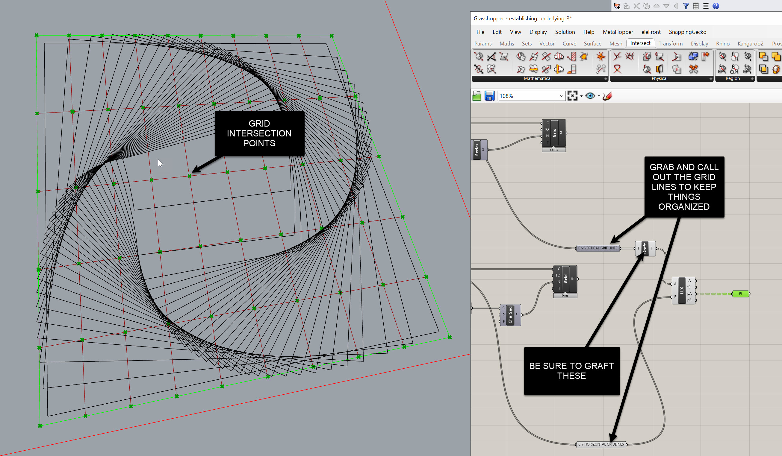
Joe’s Tip
Grafting only one set of inputs (the verticals) keeps your data trees predictable. Each branch represents one grid line and all of its intersection points, making it much easier to reference or filter later.
Moving Points Up to Each Level
Once we have the grid intersection points, we need to replicate them up through the building — one set of points per level.
-
Go back to your floor slab definition at the top of your script.
We previously extracted the Z-values from each slab to determine level heights.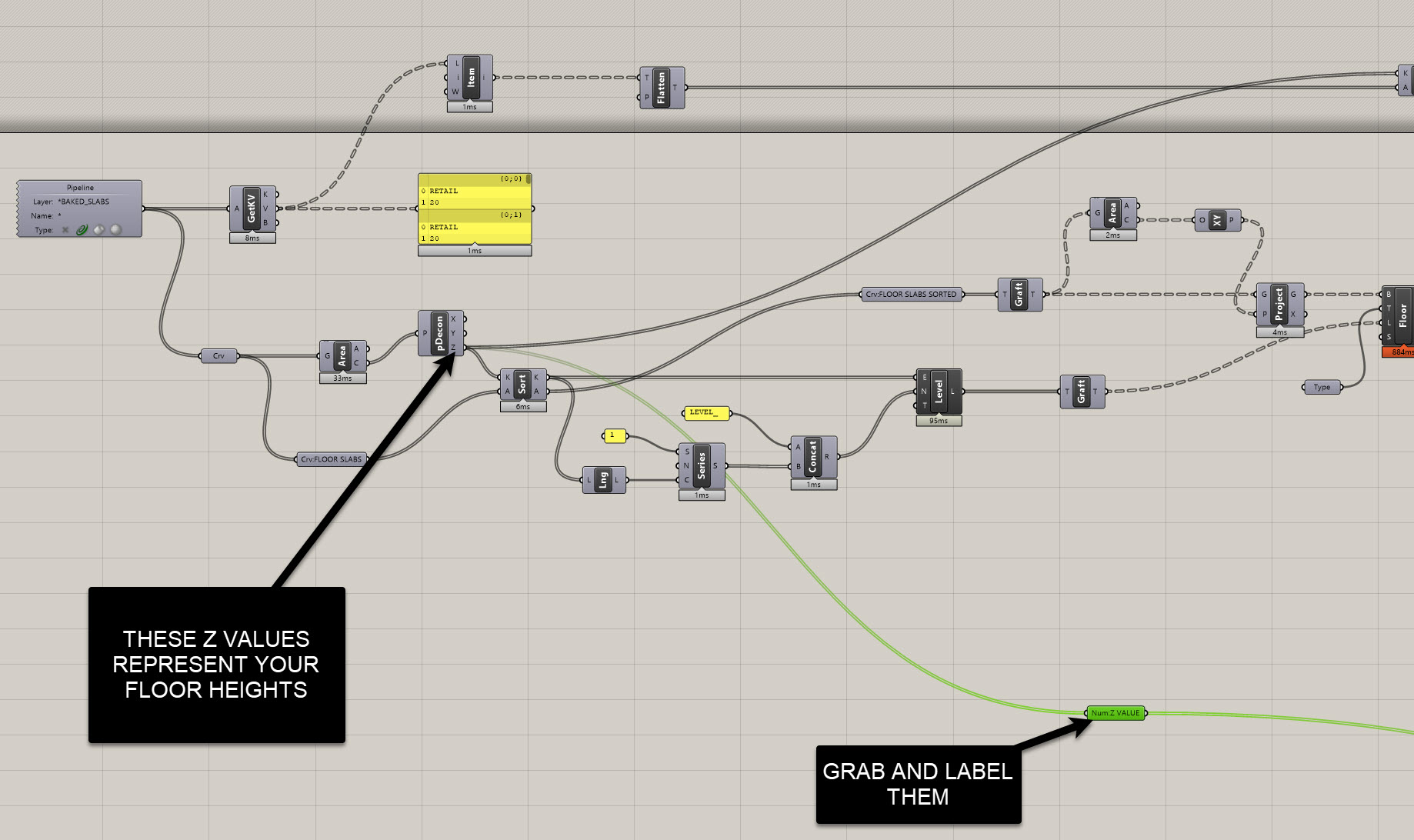
-
Use those Z-values to construct XY planes at each level.
- Create a
Construct PointusingX=0,Y=0, andZfrom each floor level. - Plug those into an XY Plane component to generate one plane per level.
- Create a
-
Then use Orient to copy your grid intersection points to each plane.
- Base Plane: World XY
- Target Plane: Each level plane
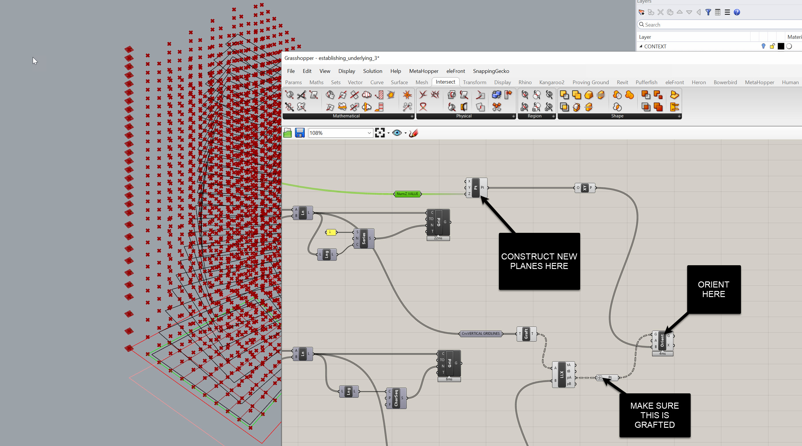
Now you’ll have a full set of intersection points per level — the base positions where columns will go.
Creating Base and Top Points
Each column will need two points: one for the base and one for the top.
- The base points are the ones you just created at each level.
- For the top points, we’ll move the base points up by the floor-to-floor height, minus the slab thickness.
To do this:
- Pull the floor-to-floor height from your user values (the same way we previously got program data).
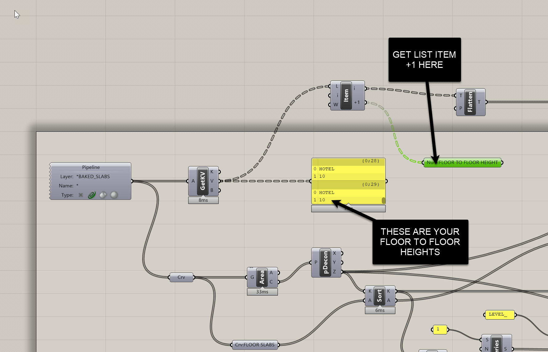
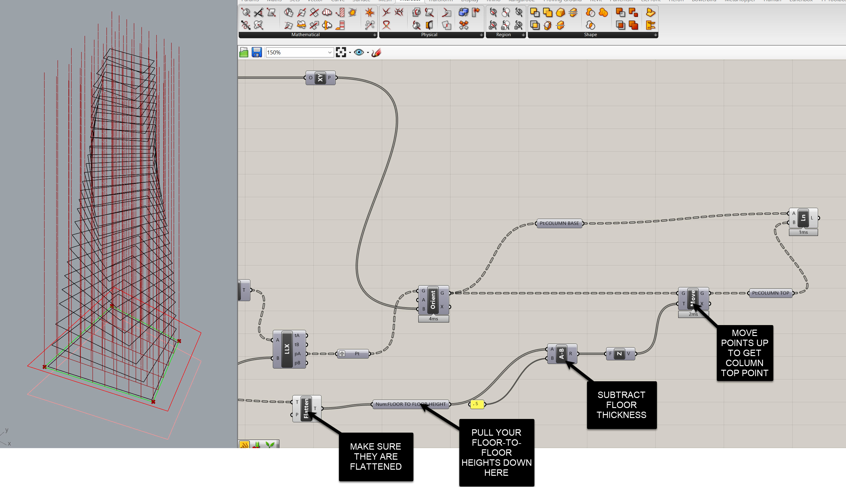
This gives you a clear pair of point sets — base and top — with identical tree structures.
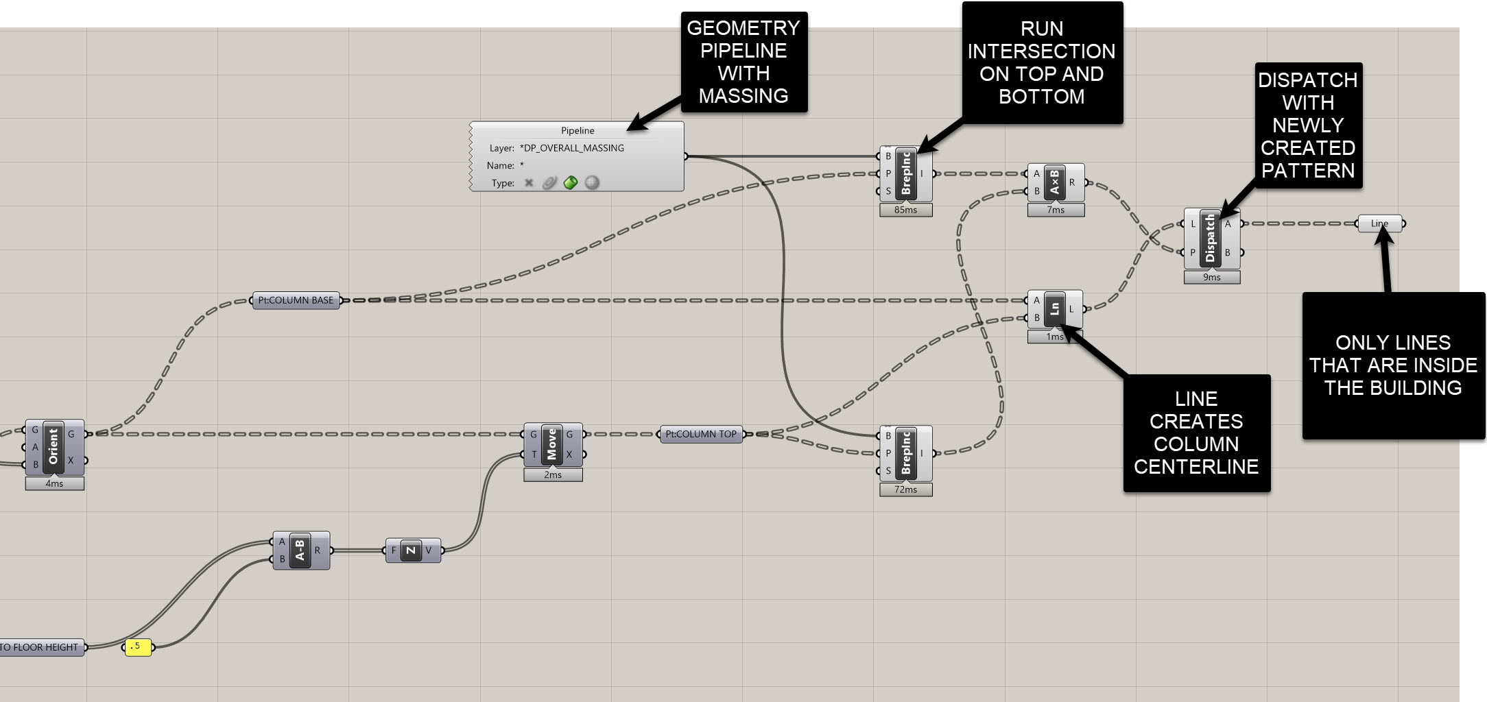
Drawing Column Centerlines
Now that we have base and top points, it’s time to connect them.
- Use the Line component.
- Start = Base points
- End = Top points
You should now see a clean grid of column centerlines extending throughout your building.
Culling Columns Outside the Massing
At this stage, we likely have some columns that fall outside of our building volume.
Let’s remove those automatically so we only keep structural elements that exist within the building envelope.
-
Reference the building massing
Use a Geometry Pipeline to pull in your massing Brep (from your “Overall Massing” layer). -
Check if points are inside
- Use the Point in Brep component twice — once for the base points and once for the top points.
- Each will output a list of
True/Falsevalues.
-
Combine the results
- Multiply the two Boolean lists together.
- Any column whose base and top both fall inside the massing will produce a
1. - Any column that’s partially or fully outside will produce a
0.
-
Cull or Dispatch
- Plug the result into a Dispatch component.
- Input the list of column lines as the geometry to filter.
- The “True” output gives you only the valid, inside columns.
Joe’s Tip
Booleans can double as numbers in Grasshopper. MultiplyingTrue/Falselists (1 × 0) is a quick way to get a clean binary filter — no need to overcomplicate the logic.
Sending to Revit
Now to create actual Revit columns from your centerlines:
- Use the Add Structural Column component from Rhino.Inside.Revit.
- Connect your filtered column lines to the input.
- Add a Type node and right-click to select your preferred Revit column family (e.g. Concrete - Rectangular or Steel - Wide Flange).
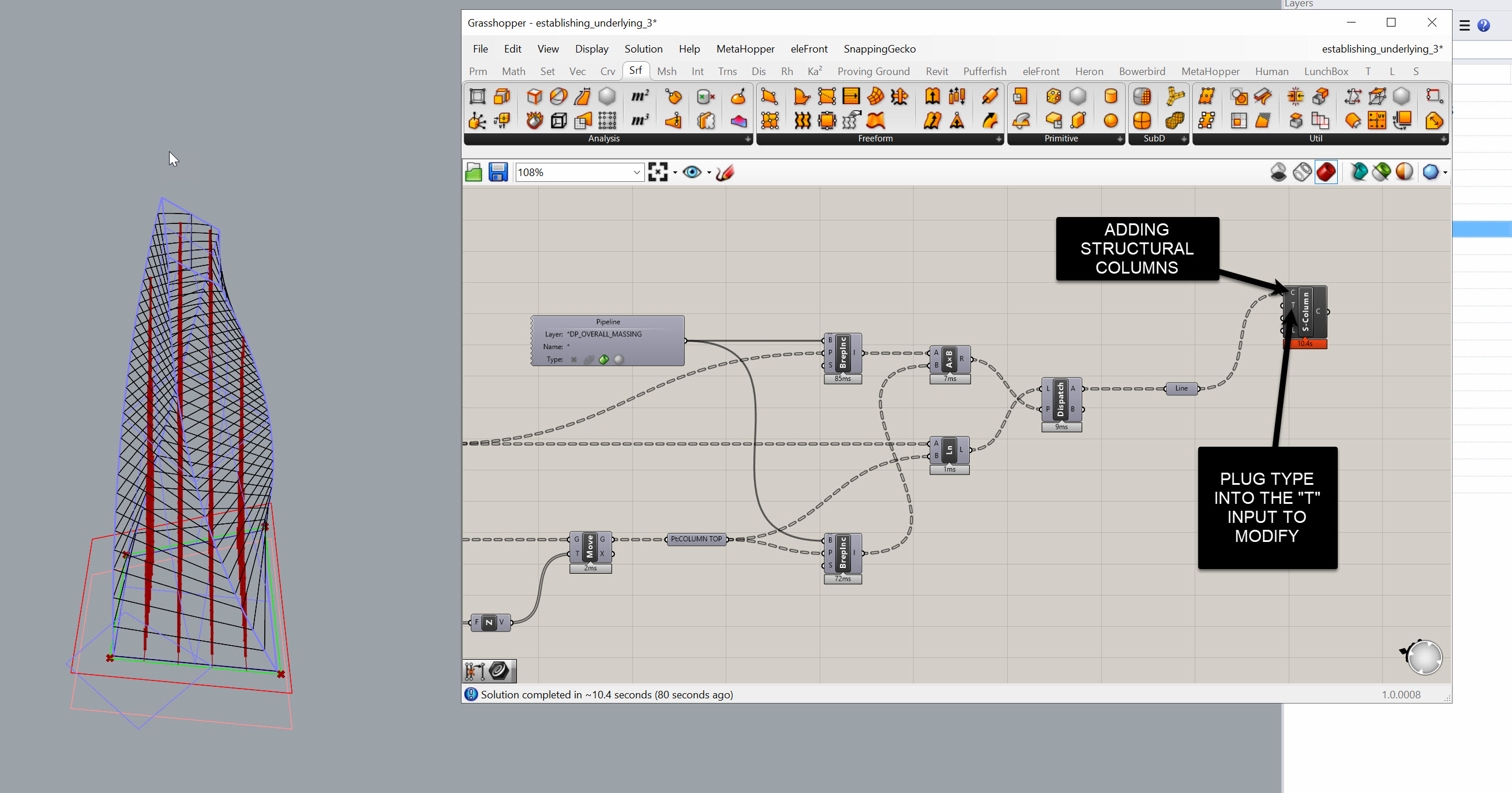
Changing the type node will automatically update all placed columns.
Side Challenge
Try using different massing volumes (like Retail, Office, or Hotel) instead of a single overall mass.
Use the Point in Brep test against each program volume, and assign unique Revit column types for each one.
This builds a program-aware structural system that updates dynamically as your model evolves.
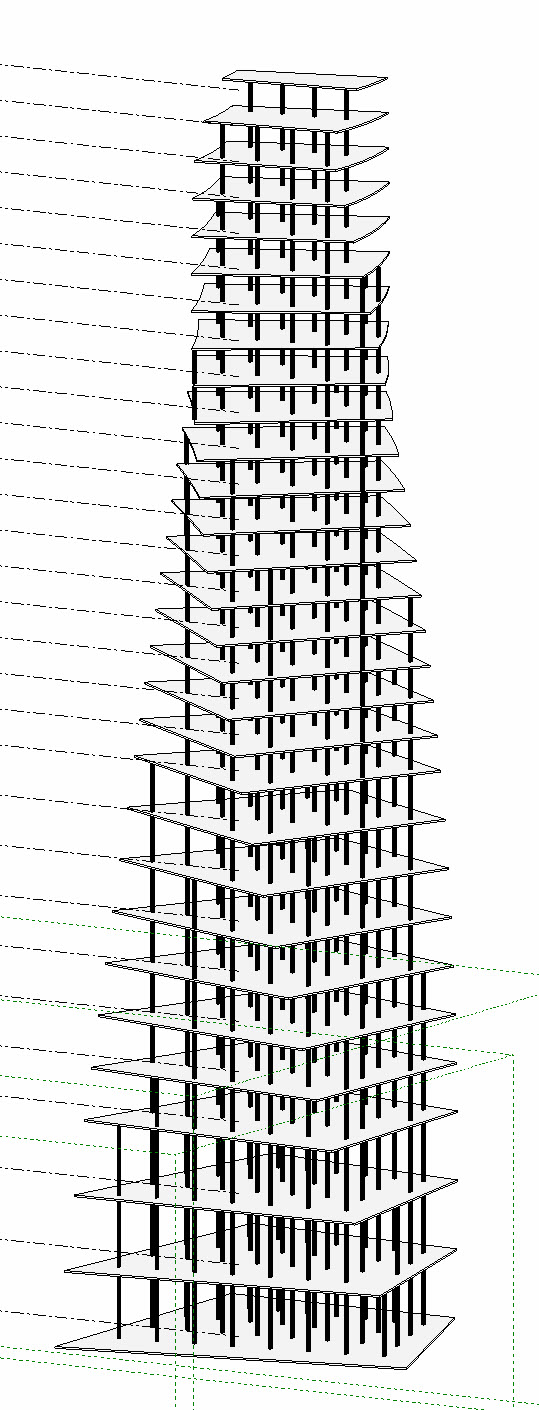
Summary
At this point, you should have:
- Grid intersections structured by data trees
- Points replicated at each floor level
- Column base and top points with consistent organization
- Clean centerlines filtered to only those inside the building
- Automated Revit column creation
This workflow establishes the foundation for a fully parametric structural system that automatically adapts to your geometry and massing logic.
