Introduction to Projection
Module Summary
This module will introduce the different types of projection, with a little bit of history about each. It will then go through creating a simple Make2D of the Casa Bahia Azul in each type.
What is Projection?
In the last tutorial we made plans and sections, drawings which are straightforward, undistorted, "flat." But we also want to be able to represent the depth and volume of three-dimensional space. As artists we would have complete freedom in how to conceptualize and depict space, but as designers the drawings we make are expected to be, in a sense, reversible. It's not enough for an image to represent a space, the space should be reconstructible from the image. And, of course, the image will hopefully correspond at least somewhat intuitively to the world we perceive with our eyes.
Mathematically translating three-dimensional space onto a two-dimensional plane in a reversible, legible is way called projection. In architecture we break projection into two basic categories, perspective and parallel.
Perspectival Projection
So far, unless you changed the settings of your viewport, all your 3D modeling has been done in perspective. This is a familiar way of representing space which creates an illusion of depth by depicting objects as smaller the further they are from the viewer or camera. In a perspective drawing, straight lines which are parallel in space appear to converge at "vanishing points." If the lines are parallel to the horizon, the vanishing point will also be on the horizon.
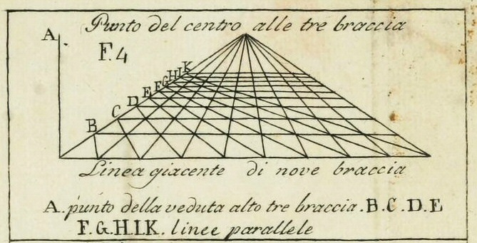
One, Two, and Three-Point Perspective
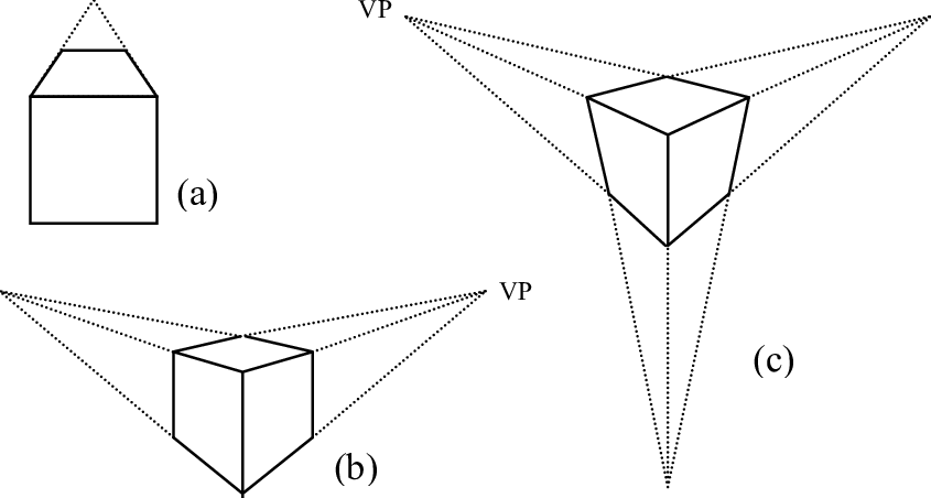
Perspective images are classified as One-Point, Two-Point, or Three-Point. For "true" projections, these categories describe the orientation of the "camera" in relation to the subject, not a difference in the construction of the projection. They also assume that the subject is mostly rectilinear, which when representing buildings is usually reasonable (at the very least, walls are usually perpendicular to a flat ground plane). The number of "points" refers to how many vanishing points there are in the drawing, if you're drawing a simple box.
One-Point Perspective
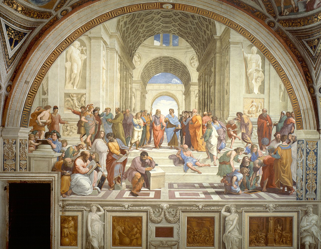
In a one-point perspective drawing, the view is parallel to both the ground and one of the main primary axes of the subject (and, therefore, is perpendicular to the third axis). The result is that only lines moving away from the viewer converge at a point. This creates the kind of classical, balanced image favored by the Renaissanice painters who were first experimenting with perspective.
Two-Point Perspective
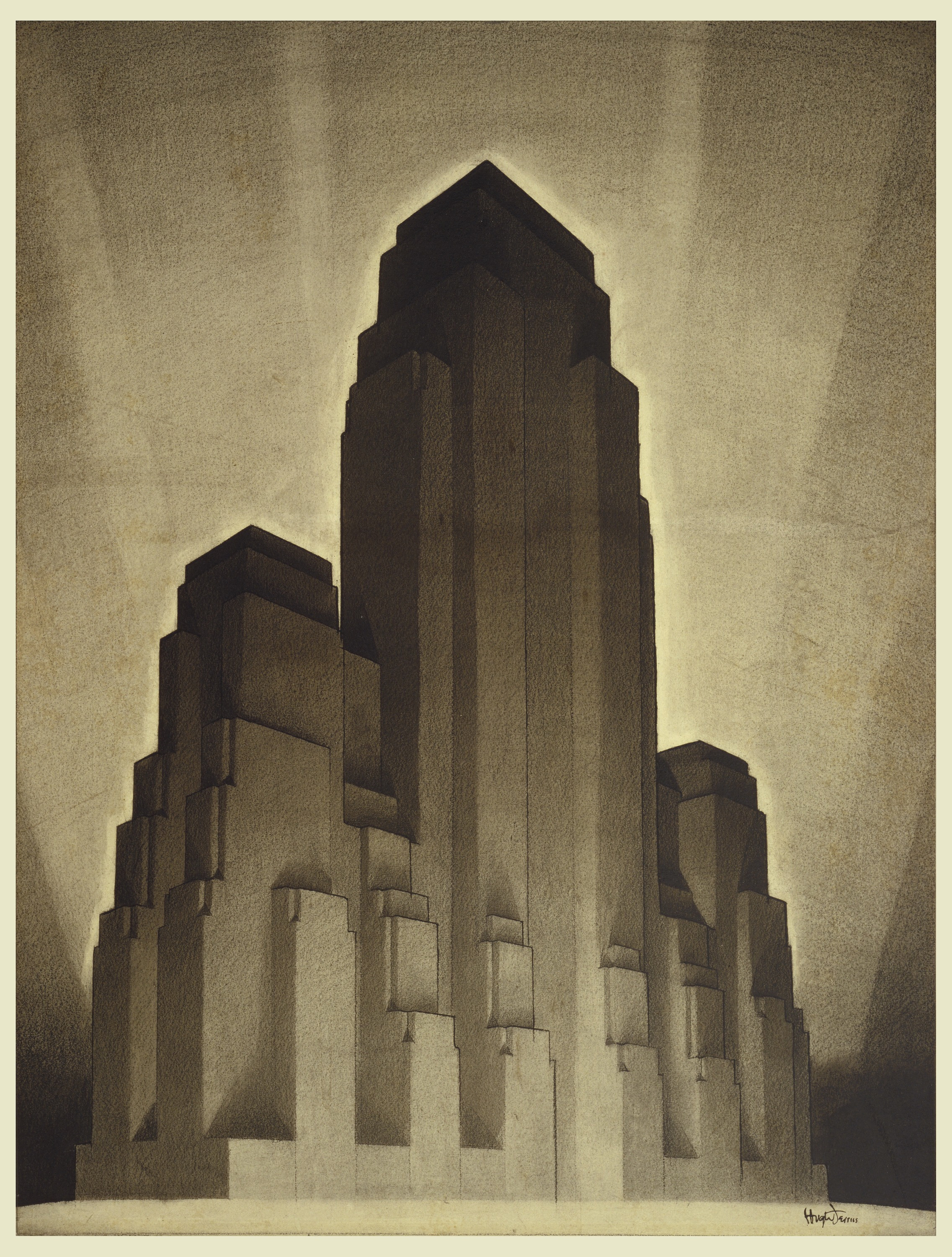
In a two-point perspective vertical lines don't converge, but the two primary horizontal axes each have a vanishing point. In a "true" two-point perspective the line-of-sight is parallel to the ground. However there's a general preference for this type of image over three-point perspectives, so often vertical lines will be drawn parallel even if the camera is looking slightly up or down. When drawing tall buildings this can have a dramatic, imposing effect.
Three-Point Perspective
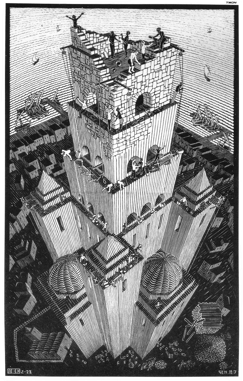
If the angle of the camera doesn't align with any of the primary axes of the subject, the result is a three-point perspective. This is typically used only when someone wants to draw attention to the fact that the view is aimed upwards or downwards, for instance to dramatize the height of the viewpoint. If the view is at least roughly horizontal, two-point perspective is used instead.
Parallel Projection
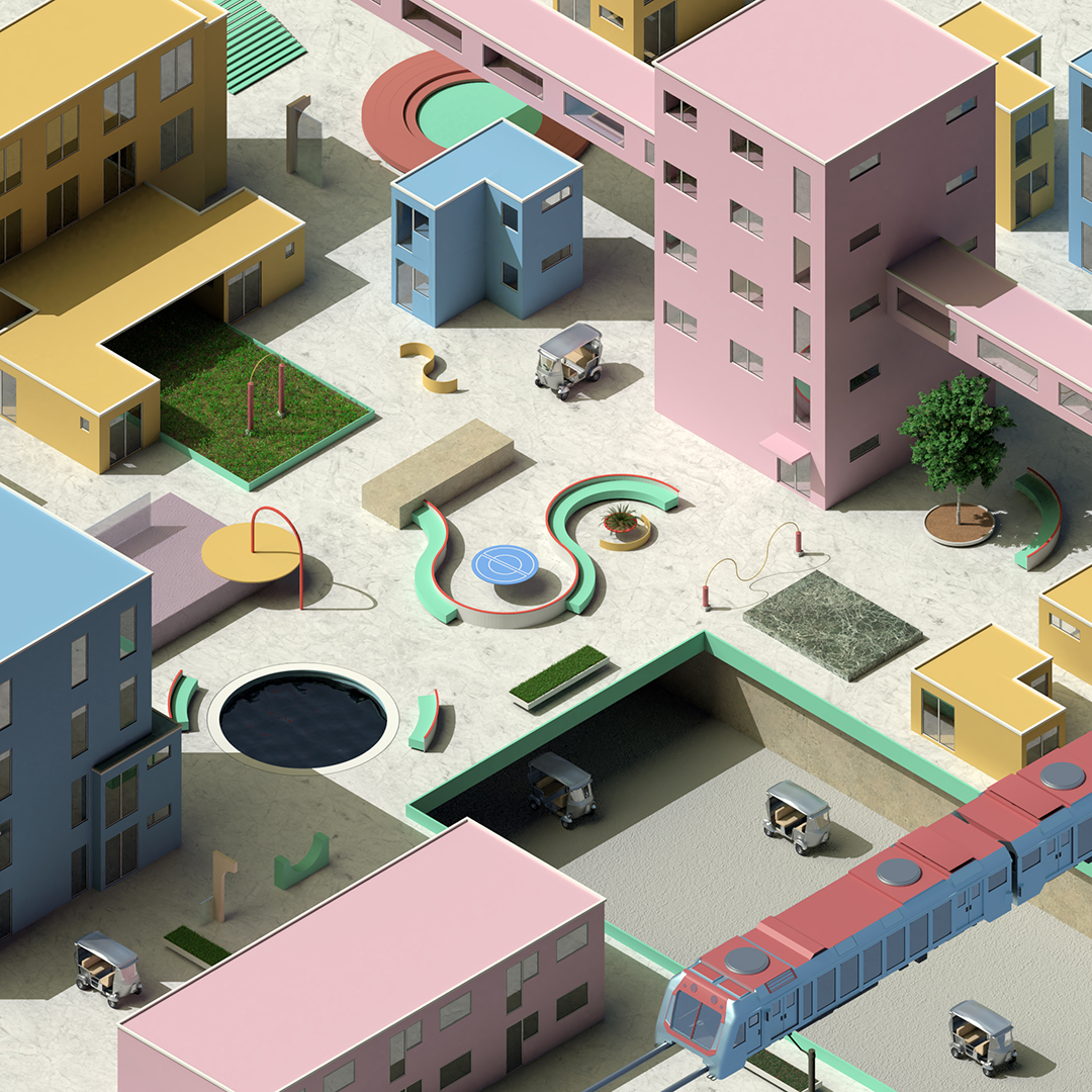
In a parallel projection, lines which are parallel in 3D space stay parallel on the page, and the size of objects isn't affected by their location in space. Strictly speaking the plan and section we created in the last module used parallel projection, with the constraint that the camera was oriented perpendicularly (orthogonally) to one of the faces of our building. But parallel projection can be used from other points of view as well.
Parallel projection sacrifices the immersive illusion of depth in favor of dimensional and geometric consistency. The sense that parallel projection was more objective, or scientific, made it a favorite of designers in the modernist era, who popularized its use in architectural drawing.
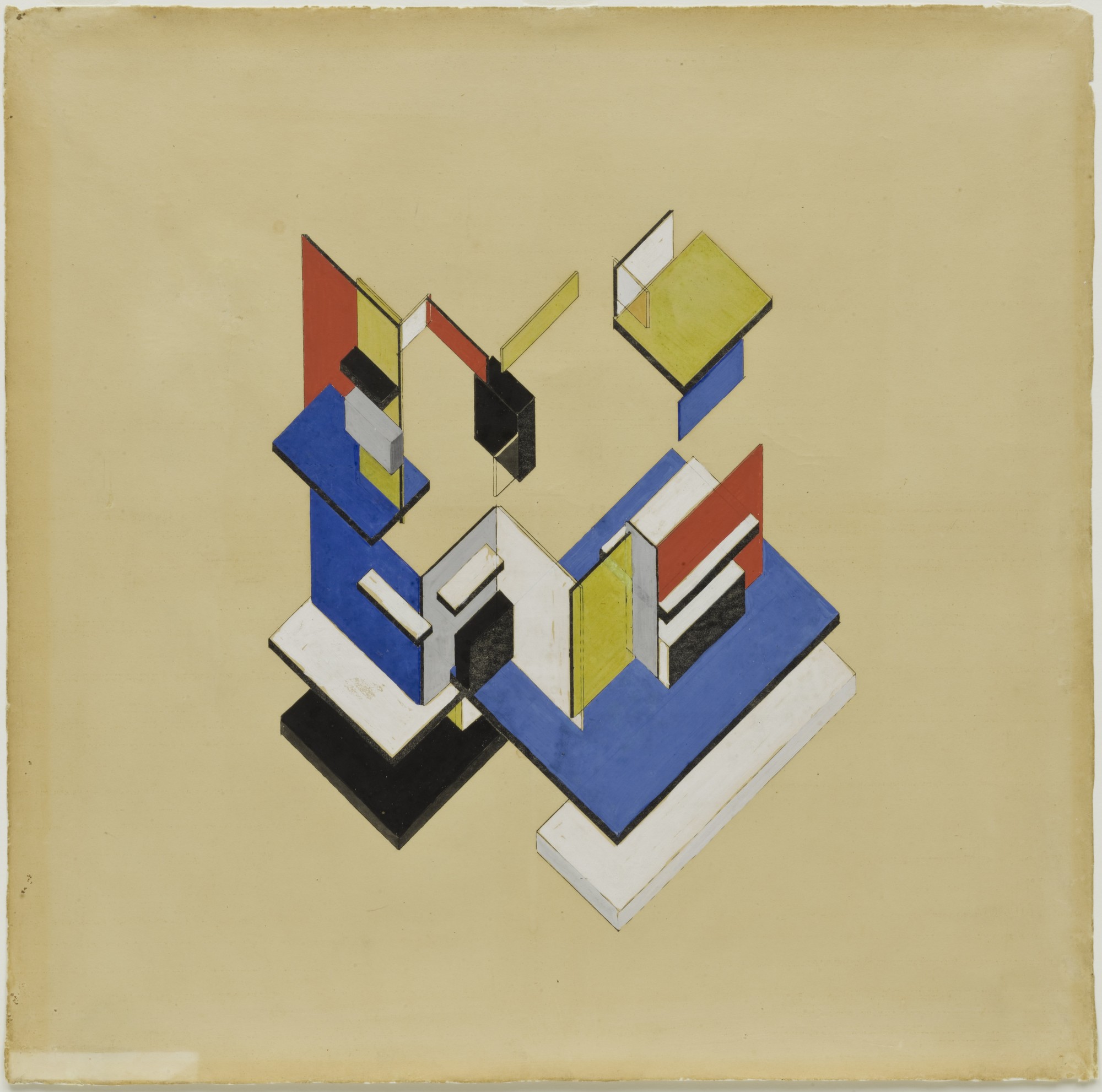
Before the 20th century, versions of parallel projection can be found in East Asian art:

and in medieval Europe:
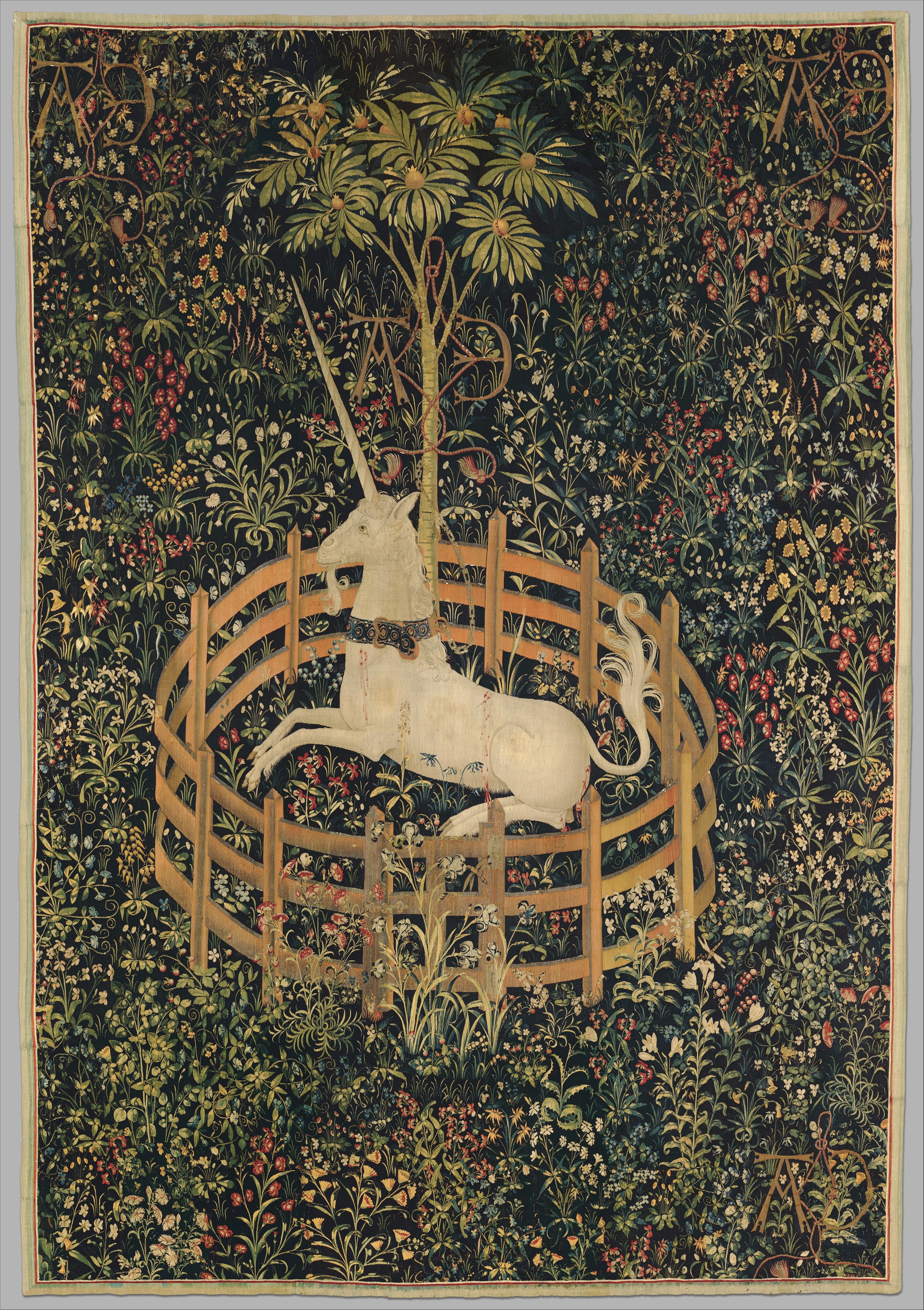
It was also common in early video games, since the unchanging appearance of objects in parallel projection was less graphically and computationally demanding than rendering in perspective:

As with perspectives, there are a few different types of parallel projection.
Isometric Projection

Isometric is the name for parallel drawings which give equal treatment to three faces of a box. A cube drawn isometrically looks like three identical rhombuses, with interior angles of 120 degrees.
Each visible edge of the cube will have the same length, just like in 3D space: in an isometric projection, relative dimensions along the X, Y, and Z axes are preserved. Diagonal lines, however, will be stretched or shortened.
The rendering at the beginning of this section and the image from SimCity 2000 both use isometric projection.
Oblique (Axonometric) Projection
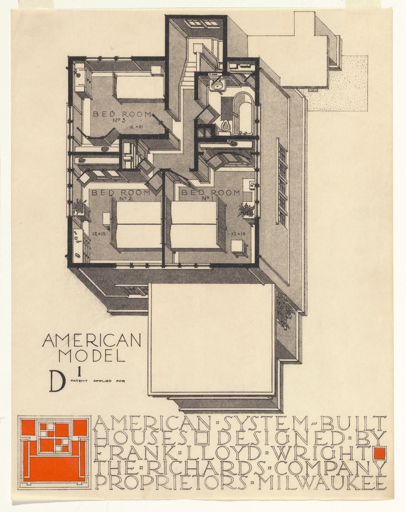
Isometric drawing preserves dimensions along the main axes, and distorts all three visible faces equally. The goal of an oblique drawing is to depict either a plan or elevation with no distortion at all, while still conveying a sense of three-dimensional space. In this drawing, for instance, all the angles and dimensions in the XY plane are depicted accurately, giving a clear description of the building's plan:
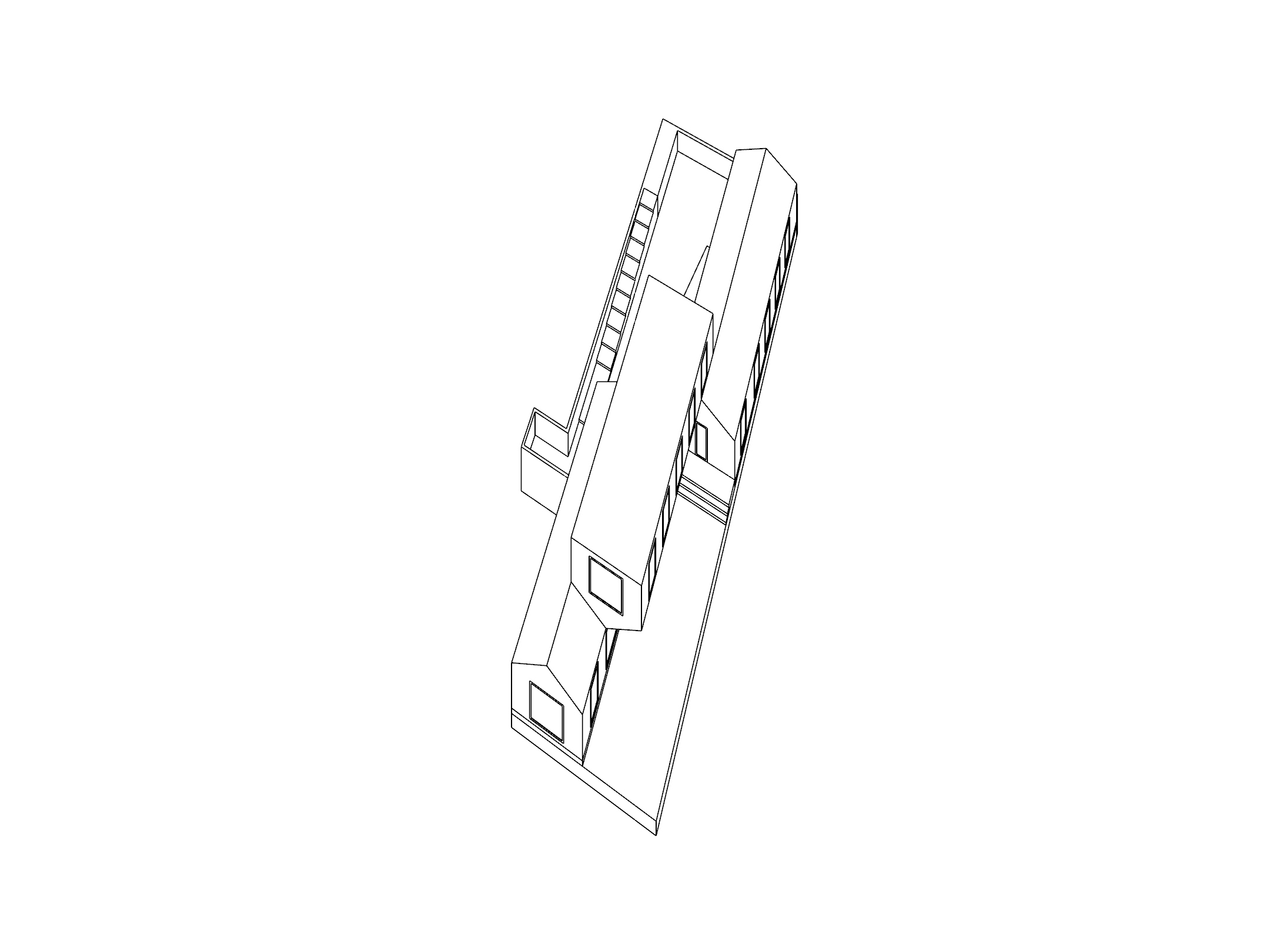
And here's one which uses the same basic projection, but with a different rotation and no plan cut:
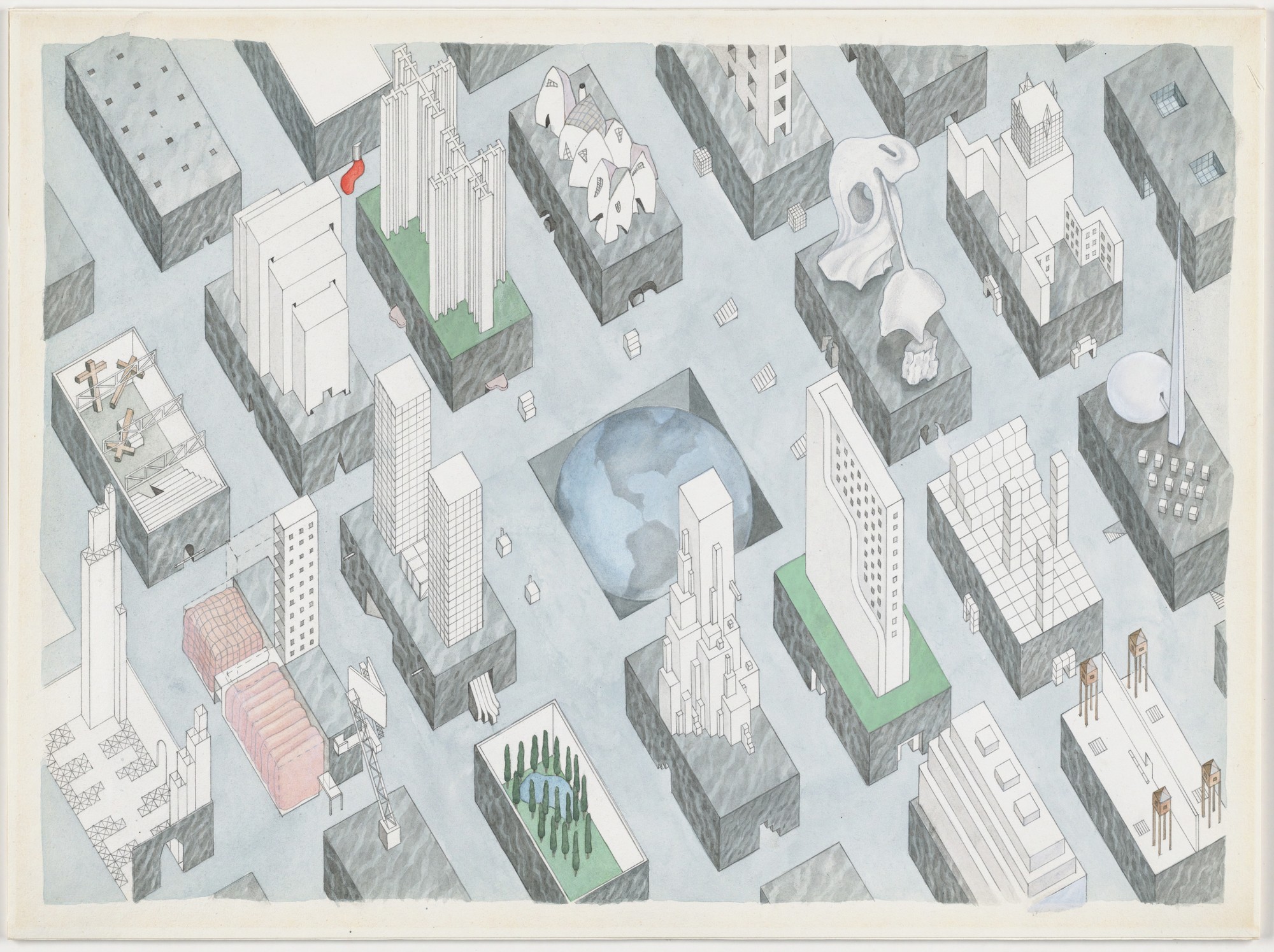
Drawings like this are commonly referred to as Axonometric, although technically this term includes all parallel projections.
Tutorial
Now let's make some projected drawings of the Casa Bahia Azul, starting with perspective.
Three-Point Perspective
If you were to pick an arbitrary view of your model and use Make2D, the result would be a three-point perspective. Try this with an aerial view:
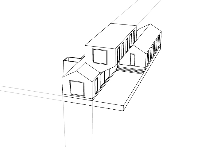
Choose two lines in the drawing which represent vertical edges, and coninue them until they meet. Then do the same with edges that were on the X and Y axes.
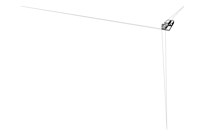
These are the three vanishing points of your three-point perspective.
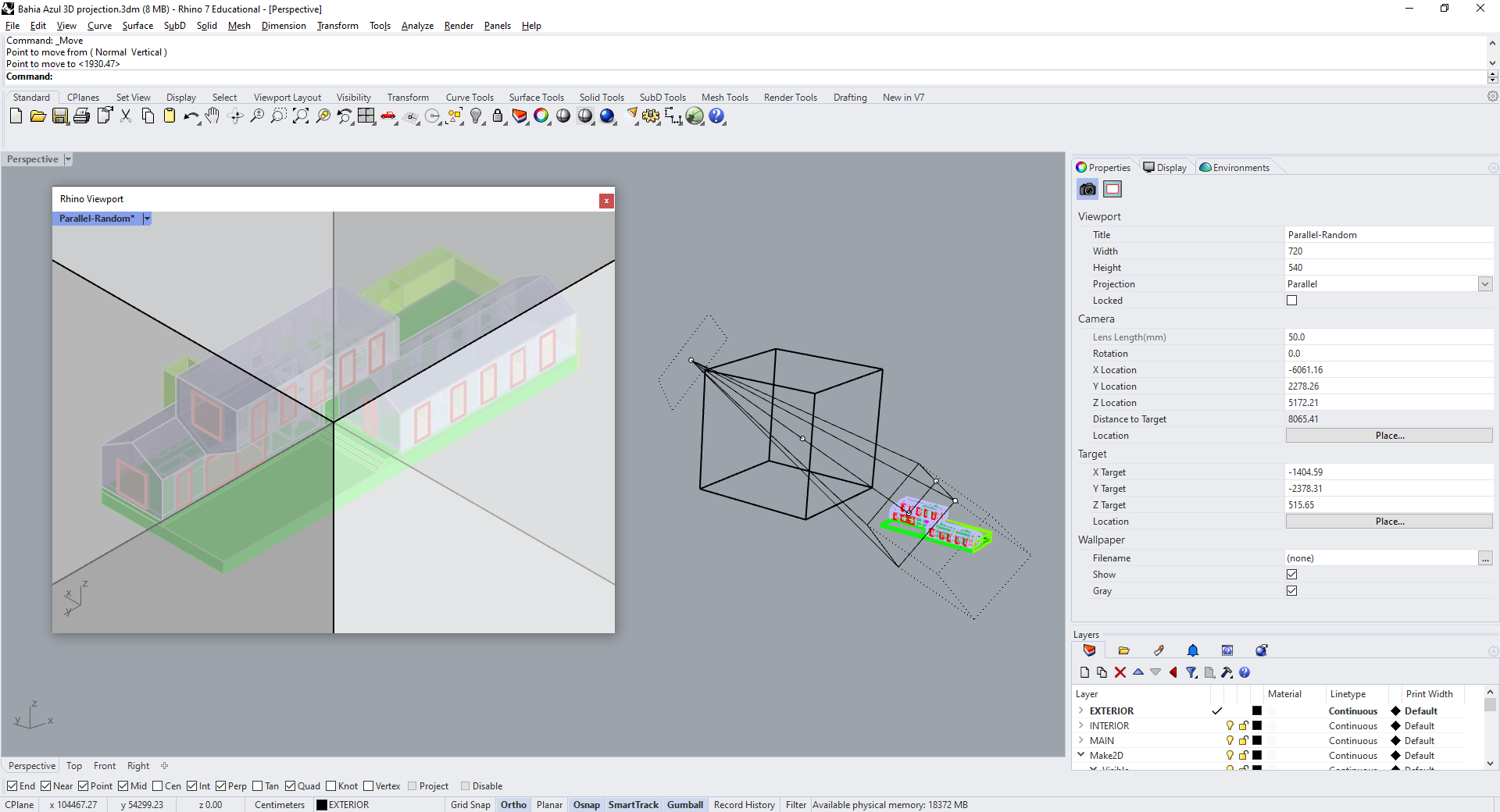
Let's set up a view with a more deliberate relationship to the building. First, while in Perspective view, use NewFloatingViewport to create a new window: we'll use this to see our output view, and the main viewport to move our camera around. In the floating viewport, use the Camera command and choose "Show" in the command prompt. The camera, target, and cone of view will appear as objects in your other viewport.
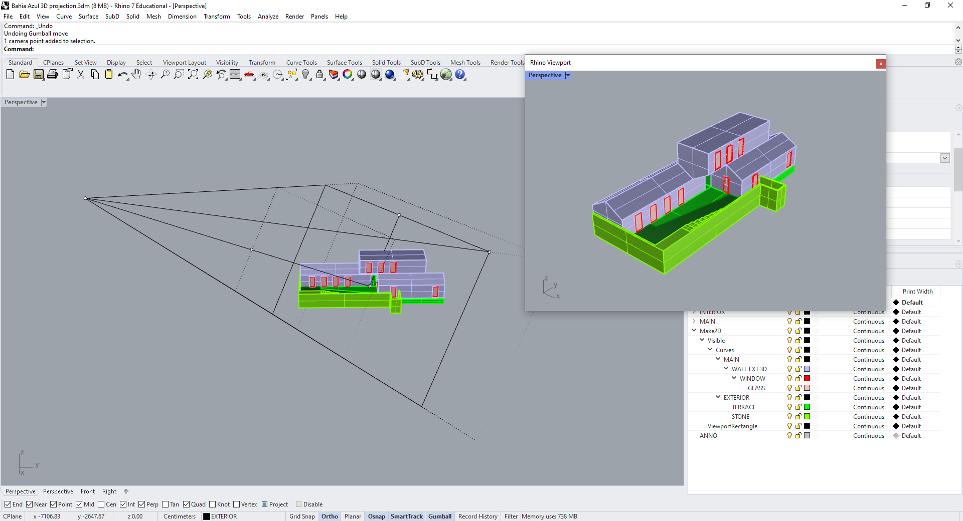
You can move the camera and target as if they were ordinary points, or move both at once using the midpoint of the line connecting them. Try this out by creating a large cube, and moving the camera and target to opposite corners of it.
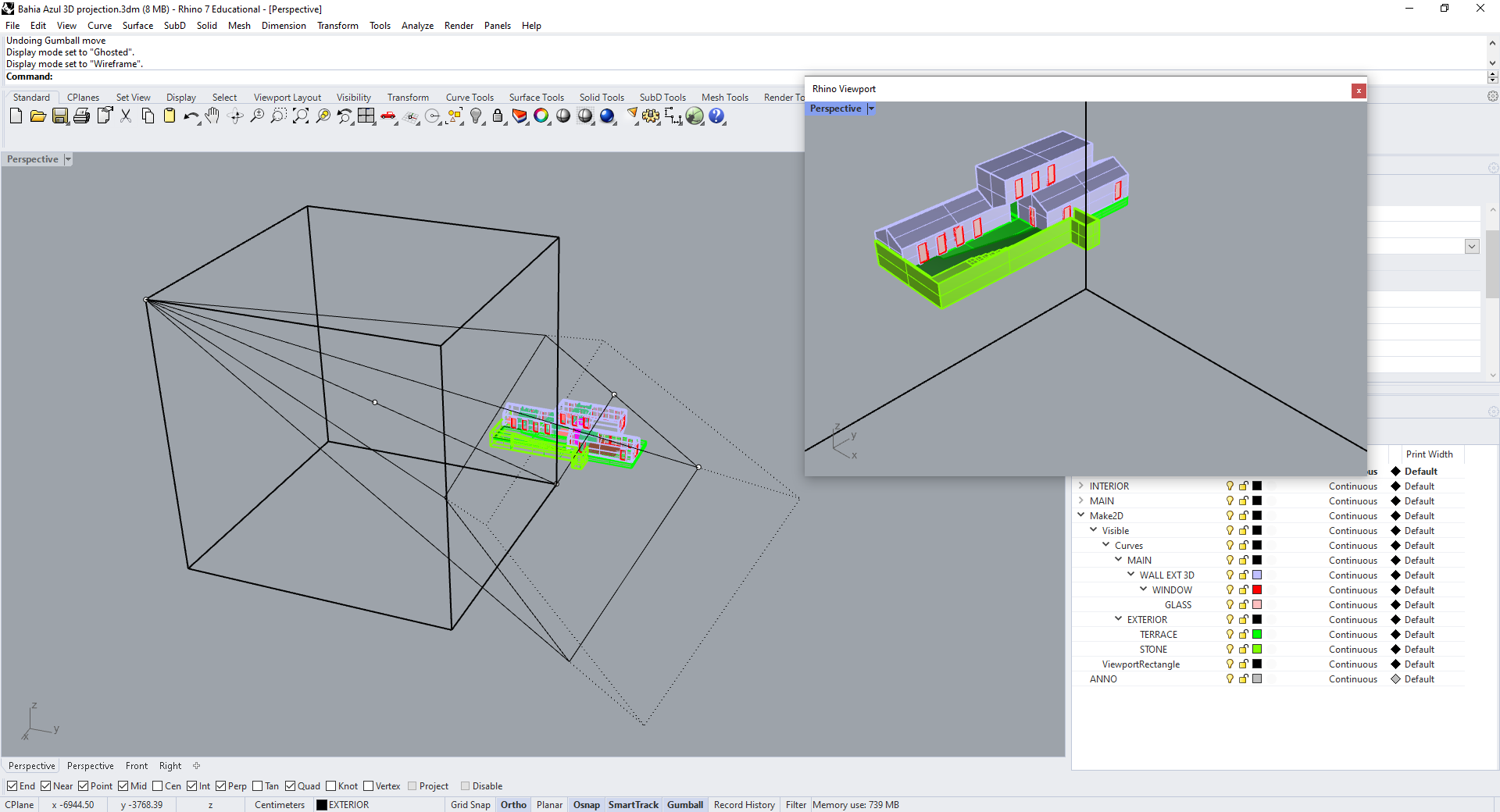
Then delete the box, and adjust the view, using the center point to move both camera and target, until the building is centered in the viewport. Once you've found a view you like, use NamedView to save it, so you can come back to it later.
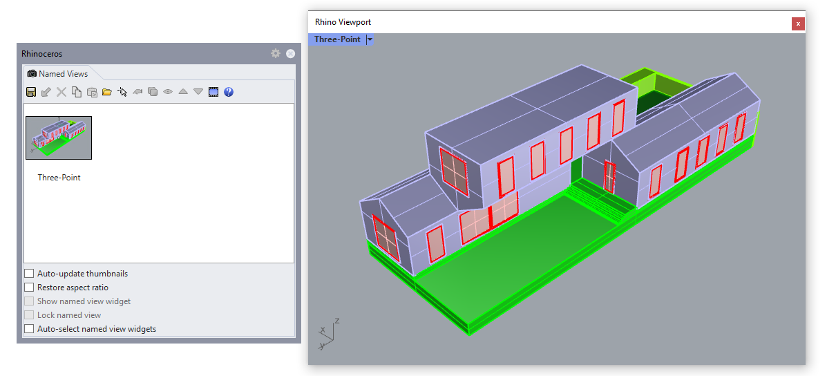
Then use Make2D again to make another three-point perspective.
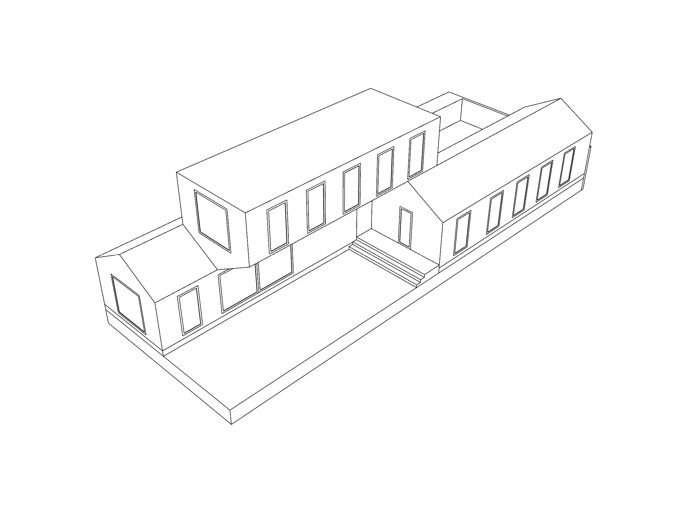
Two-Point Perspective
To construct a two-point perspective, we need our line of sight to be parallel to the ground plane, intersecting with vertical lines at a right angle. To do this, move your camera vertically so it's at the same elevation as its target.
Typically a perspective like this is drawn at eye-level, or roughly 5'-6" (168 cm) above the ground. Move the camera and target to this height, then adjust to center the model in the frame.
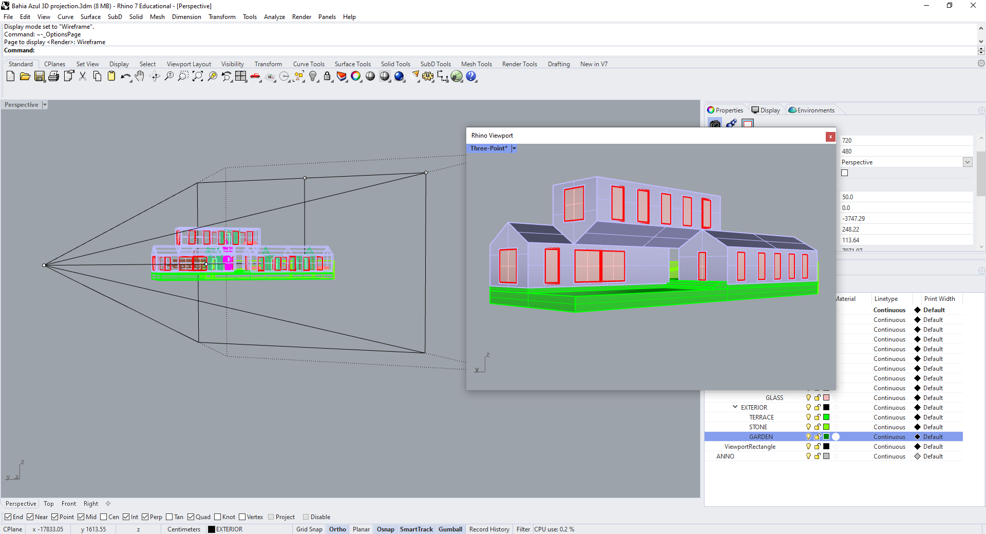
Save this view as well, then Make2D. You can check that, while you still have two vanishing points, vertical edges are now parallel.
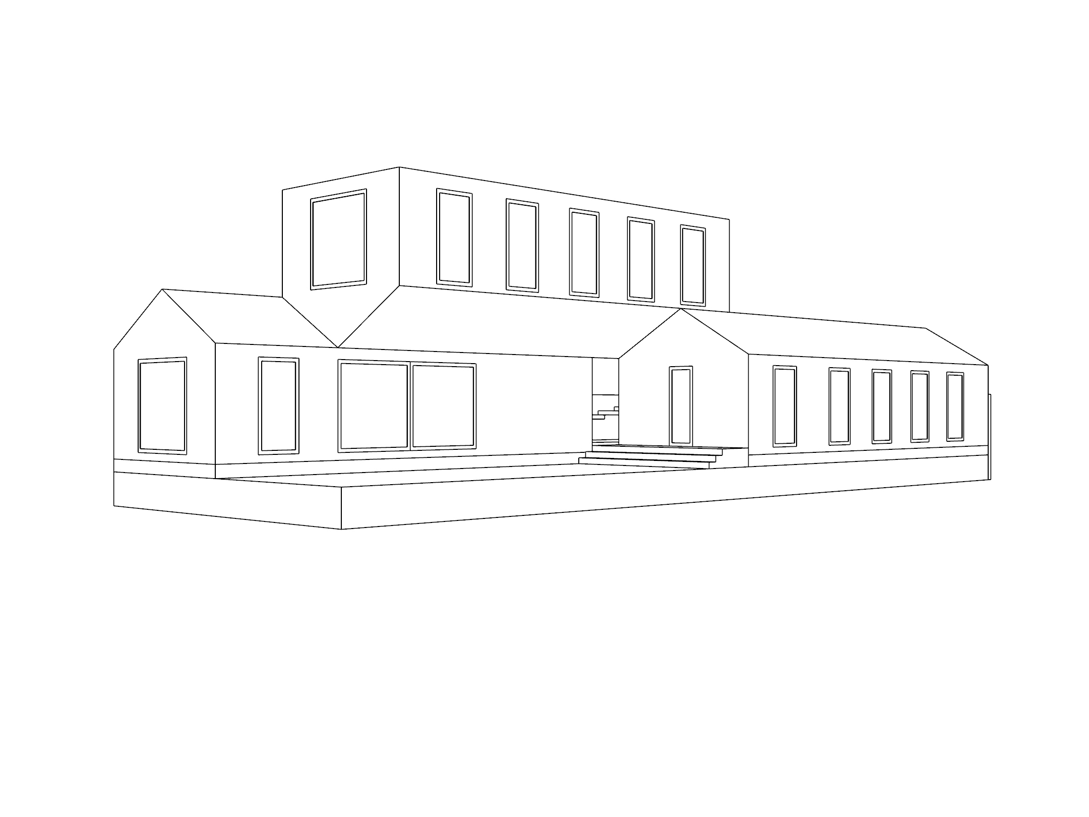
Since we set our camera at a 45-degree angle to the building, our two vanishing points will be symmetrically spaced to the left and right of the center of our image. But anywhere we place our camera in the XY plane will result in a two-point perspective, as long as we keep it at the same height as the target.
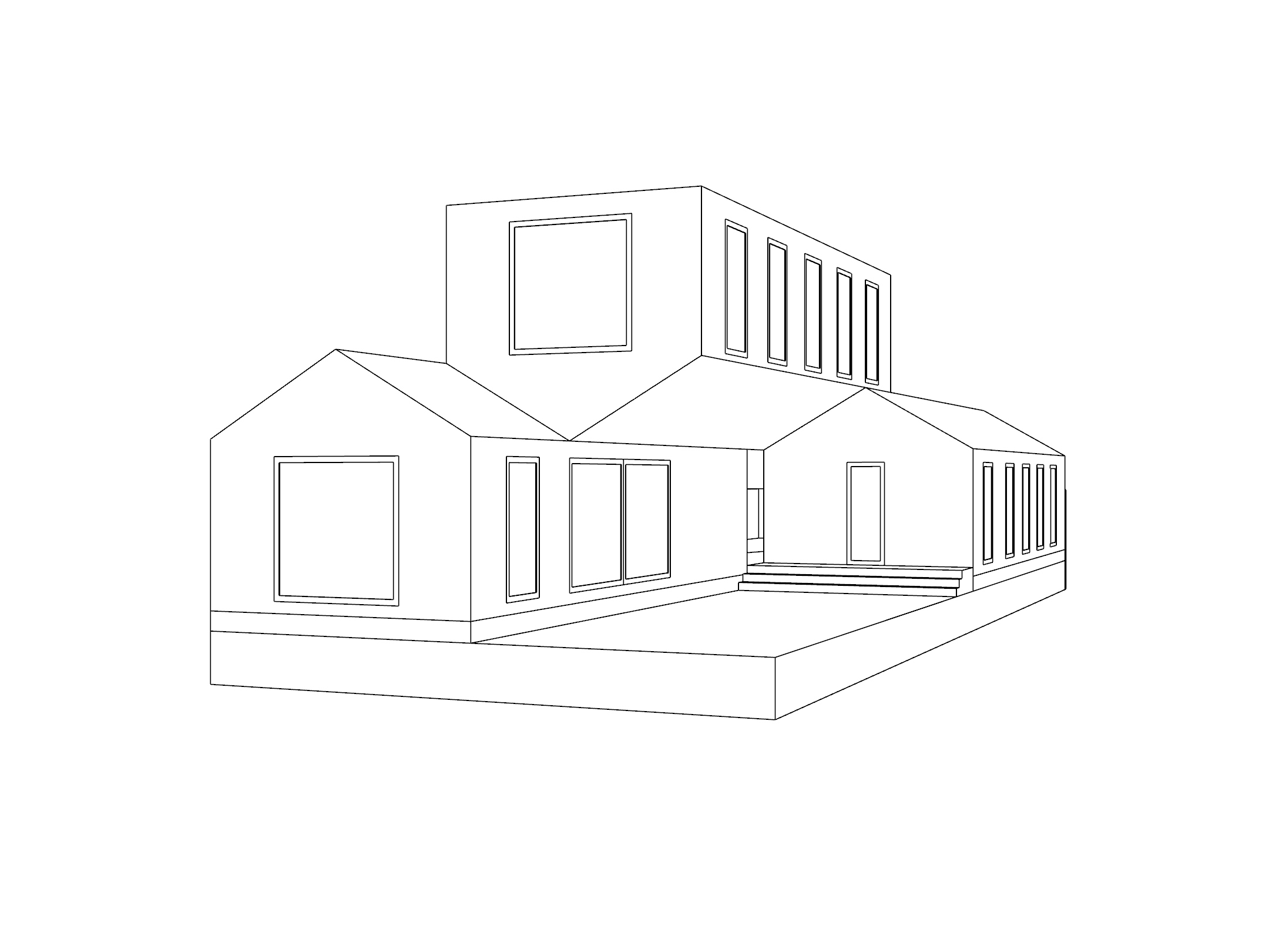
Forced Two-Point Perspective
As a general rule of thumb, a drawing with parallel vertical lines will create a more appealing composition than one where vertical lines are almost parallel, but not quite.
But sometimes it's difficult to set up a view that works perfectly as a true two-point perspective; often, for instance, there's more happening in the scene above eye-level than below, which would be easier to capture by pointing your camera upwards. For these situations, Rhino gives you the option of artificially straightening vertical lines to "force" a two-point perspective. Try moving your camera above your target, and switching to this projection in the viewport properties panel.
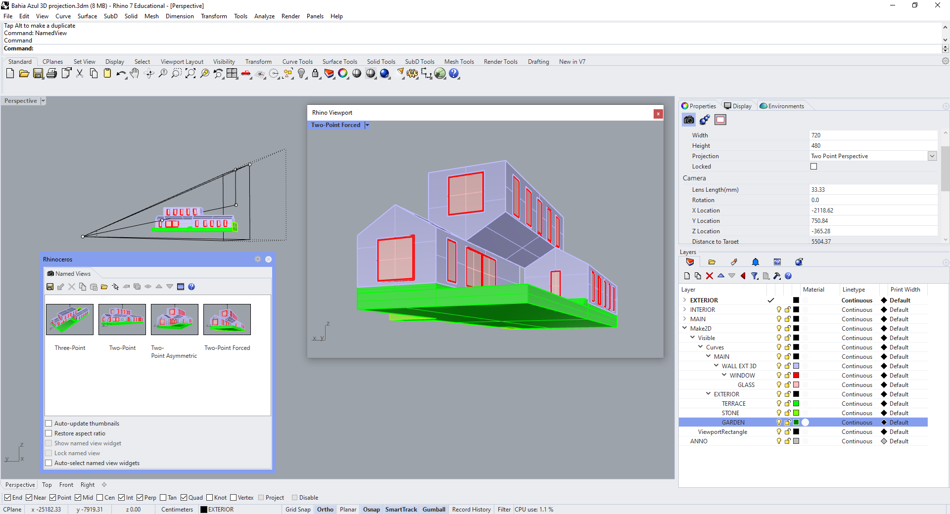
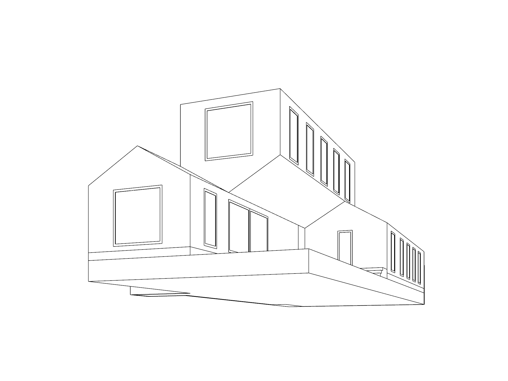
This works well if the view is already close to being a true two-point perspective. As the view diverges further and further from horizontal, the distortion becomes extreme.
One-Point Perspective
For a one-point perspective, move the camera so it's both at the same elevation as its target, and aligned with it on either the X or Y axis.
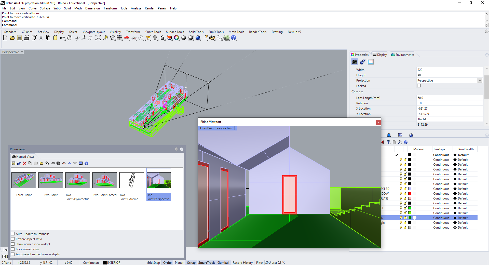
Make2D this one too, and check that you only have one vanishing point.

View Angle
Other than the placement of the camera and target, the main variable which affects a perspectival projection is the view angle. This describes the angle between the outer edges of the camera's cone of view. Look at your camera from above to see a representation of this.
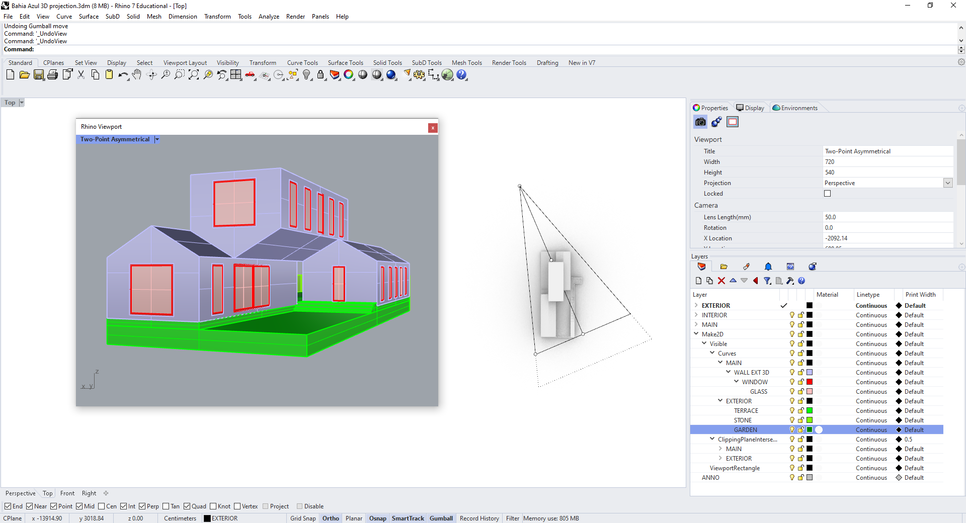
Rhino describes this angle in terms of lens length, as if you were using a physical camera. By default this is set to 50mm, which approximates the view angle of the human eye. You can adjust this value in the properties panel.
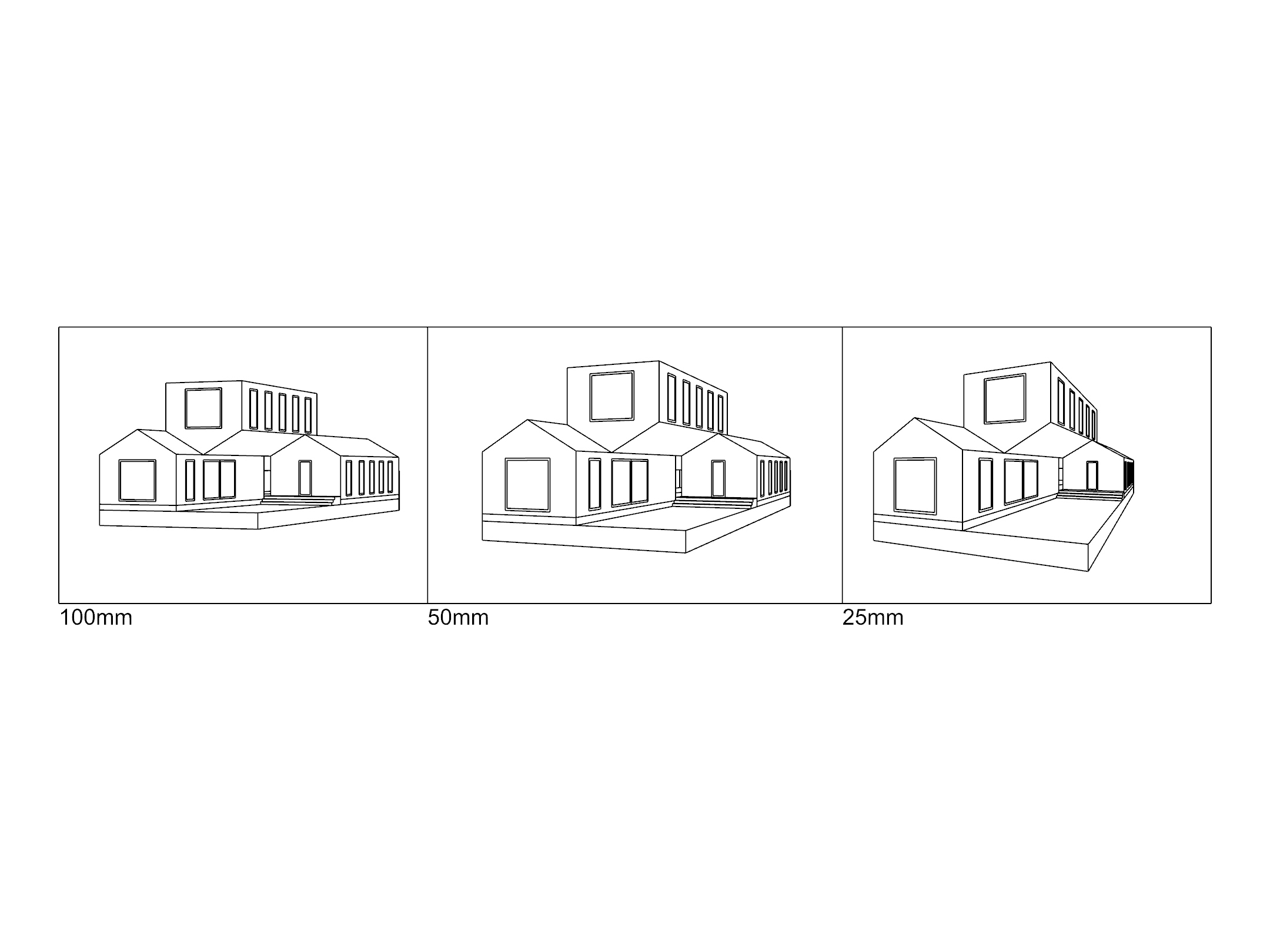
Lowering the lens length allows you to capture more of your scene from a given viewpoint, but makes the angles in the resulting image more acute. Try setting it to 25:
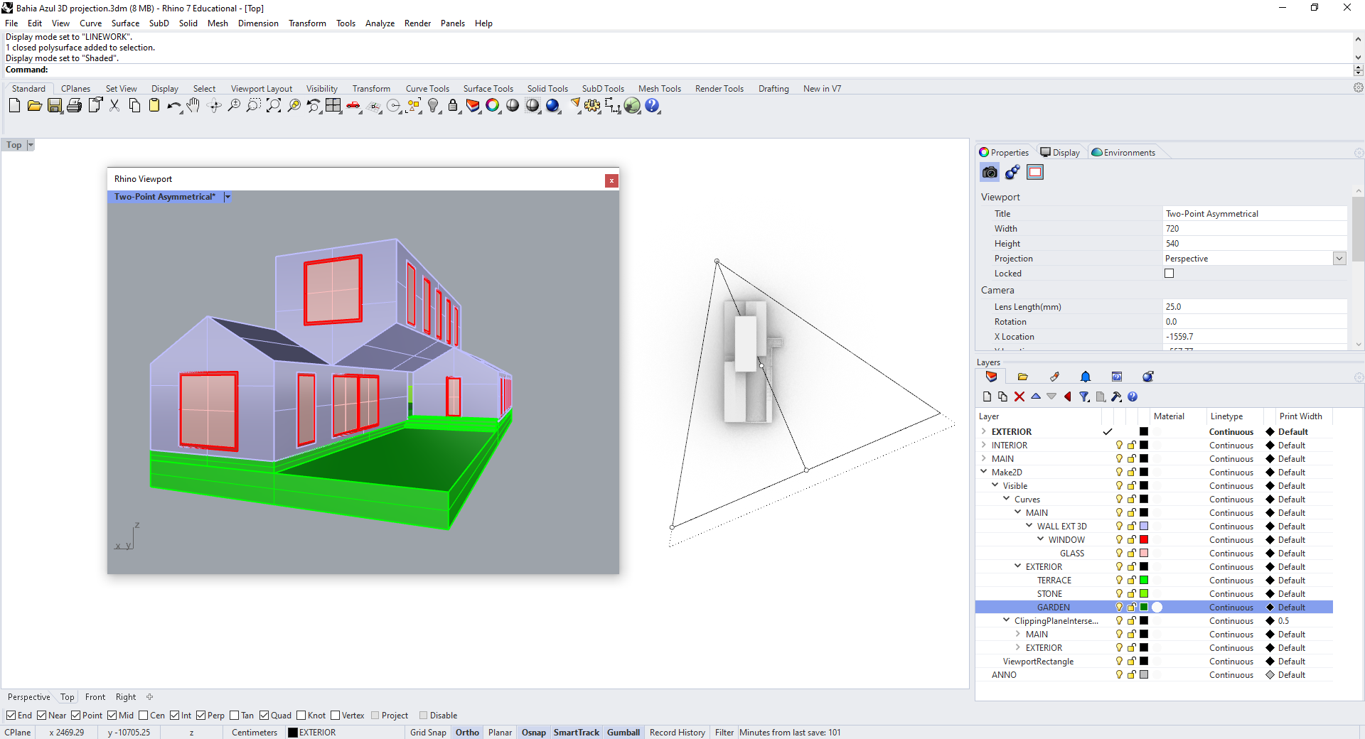
The resulting view is distorted, but a short lens length can be used deliberately to create a more dynamic image. In contrast, try raising the lens length to 100:
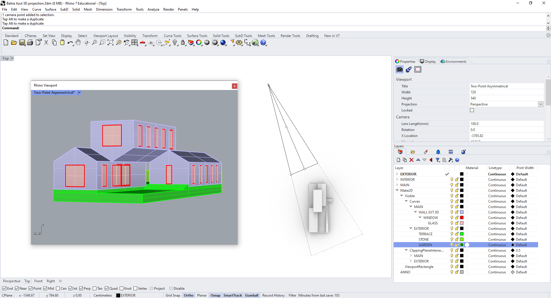
Increasing the view angle moves the vanishing points away from the center of the frame, bringing converging lines closer and closer to parallel. The resulting image appears more stable, solid. If we could place the camera infinitely far away, the lines would never converge, and the result would be parallel projection.
To use parallel projection in your Rhino viewport, select it in the properties panel:
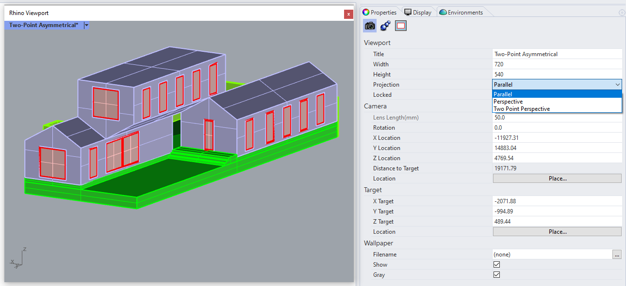
You can orbit around in this view as you would in perspective, but you'll find that a vector drawing from this view preserves parallel edges.

Isometric Projection
To set up an isometric projection, we could place our camera and target at opposite corners of a cube, just like we did earlier when working in perspective.
But Rhino saves us the trouble by including four isometric views in the "View" dropdown menu.
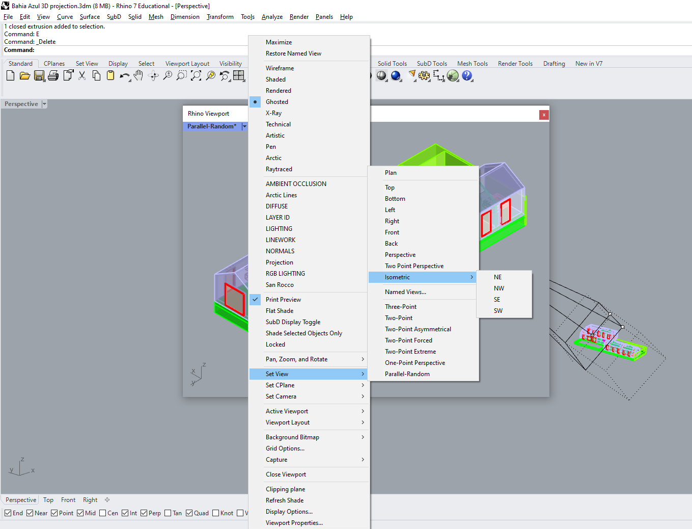
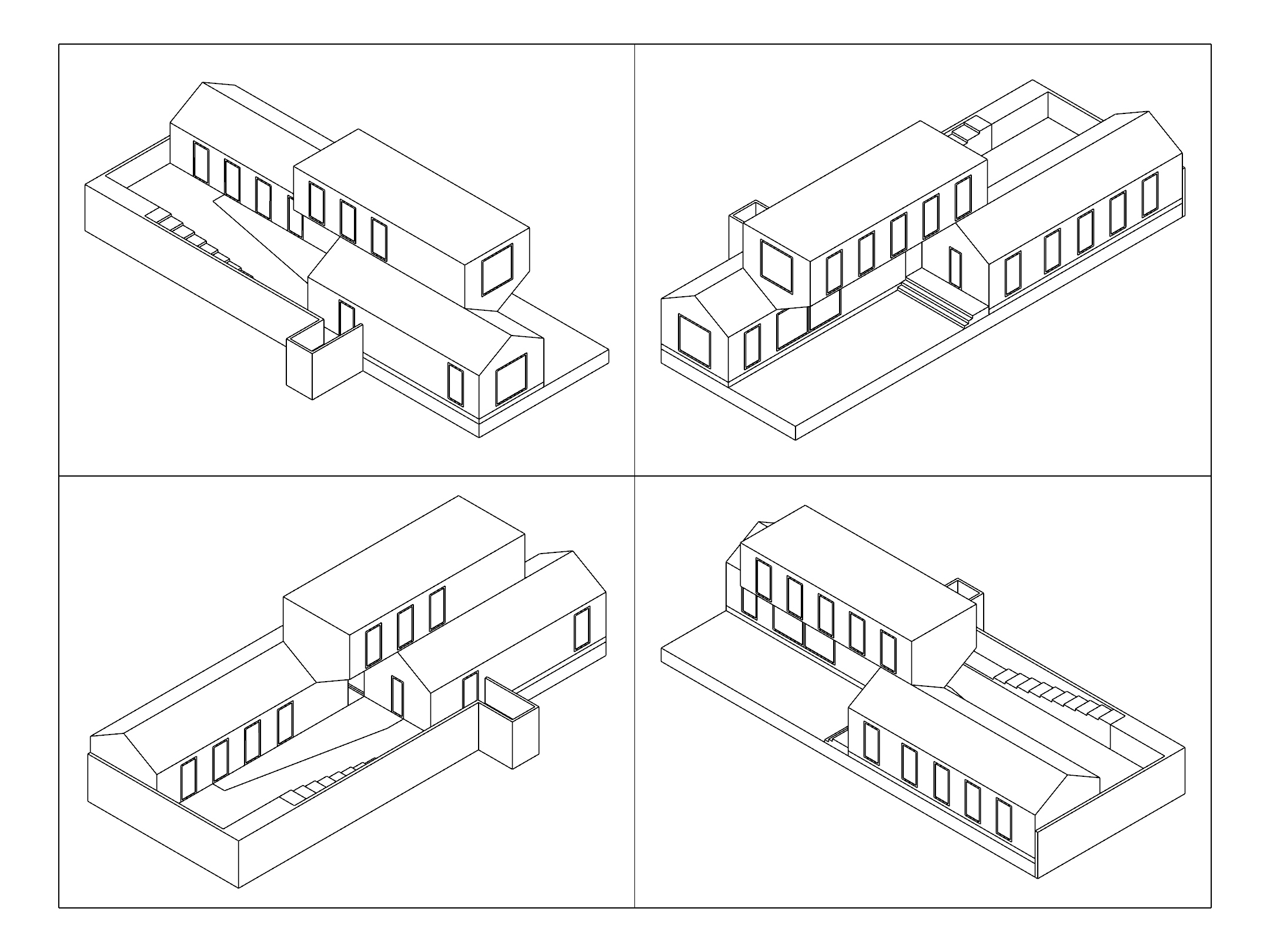
Try out each of these to make isometric drawings of the Casa Bahia Azul.
Plan Oblique
Unlike all of the perspective and parallel projections we've used so far, we can't create an oblique axonometric drawing in Rhino just by changing the settings or placement of the camera. We have to distort the actual geometry of our model. So select all of your 3D geometry, copy it to a new location in the model, and then hide the original.
Select the new geometry you just copied, switch to Right view, and then Shear it by 45 degrees.
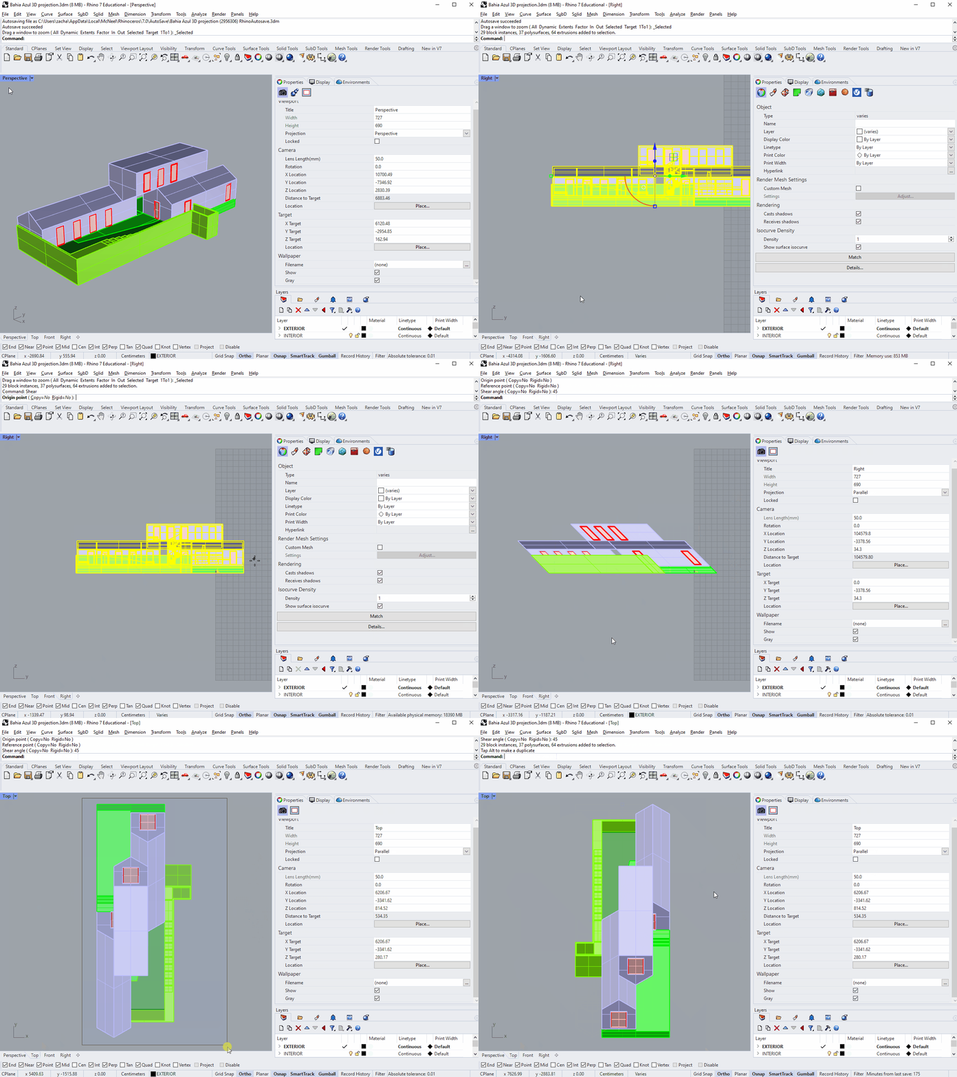
Look at this distorted model from the top, and use Make2D on it. Because we sheared the model in the horizontal plane, the plan is unchanged. And because we used a shear angle of 45 degrees, the front face of the building is also represented accurately.
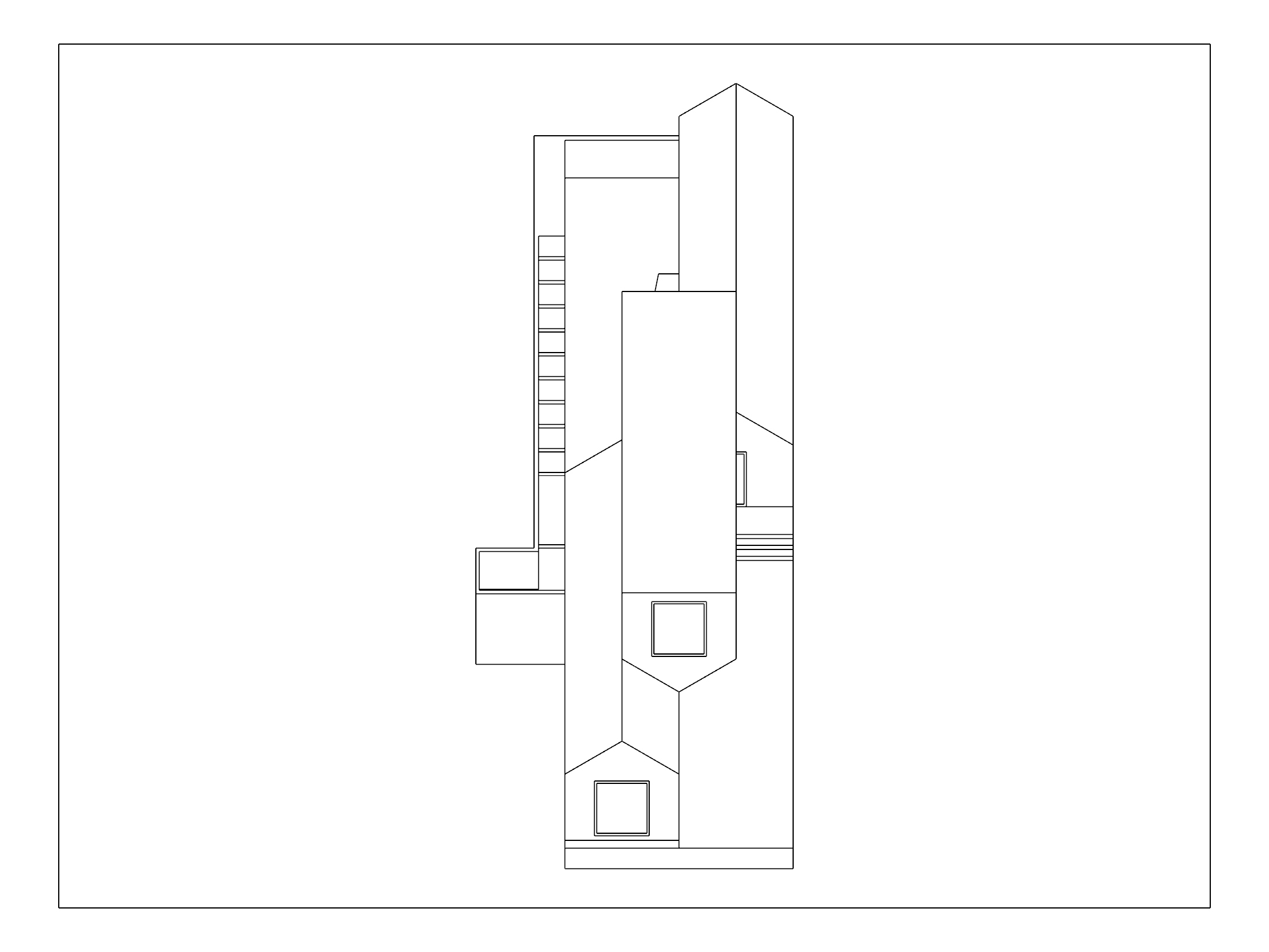
This drawing preserves both plan and elevation, but becuase it only represents two faces, it doesn't give a great three-dimensional impression of the building. Now Show your original model and create three more copies of it. But this time, rotate the copies 30, 45, and 60 degrees in top view. Select all of them, and just like before, Shear them 45 degrees when looking at them from the side. Then switch back to top view, and use Make2D again.
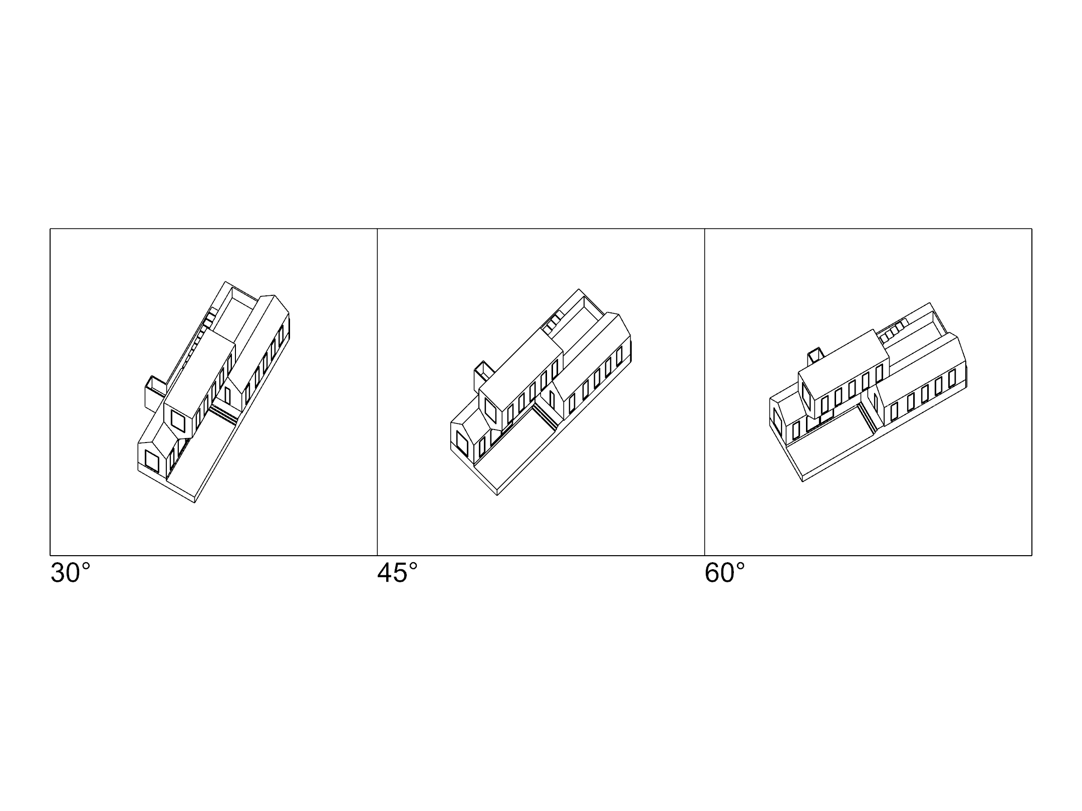
You now have three Plan Oblique drawings. Each of them has an accurate plan. The dimensions of vertical and horizontal lines are also preserved, but just like in the isometric drawing, diagonal lines in vertical planes are either stretched or compressed. The middle drawing gives equal treatment to the two elevations of the building, while those on either side privelege one face over another.
As an extra challenge, try making a plan oblique drawing that includes a plan cut, as in the Frank Lloyd Wright drawing above.
Elevation Oblique
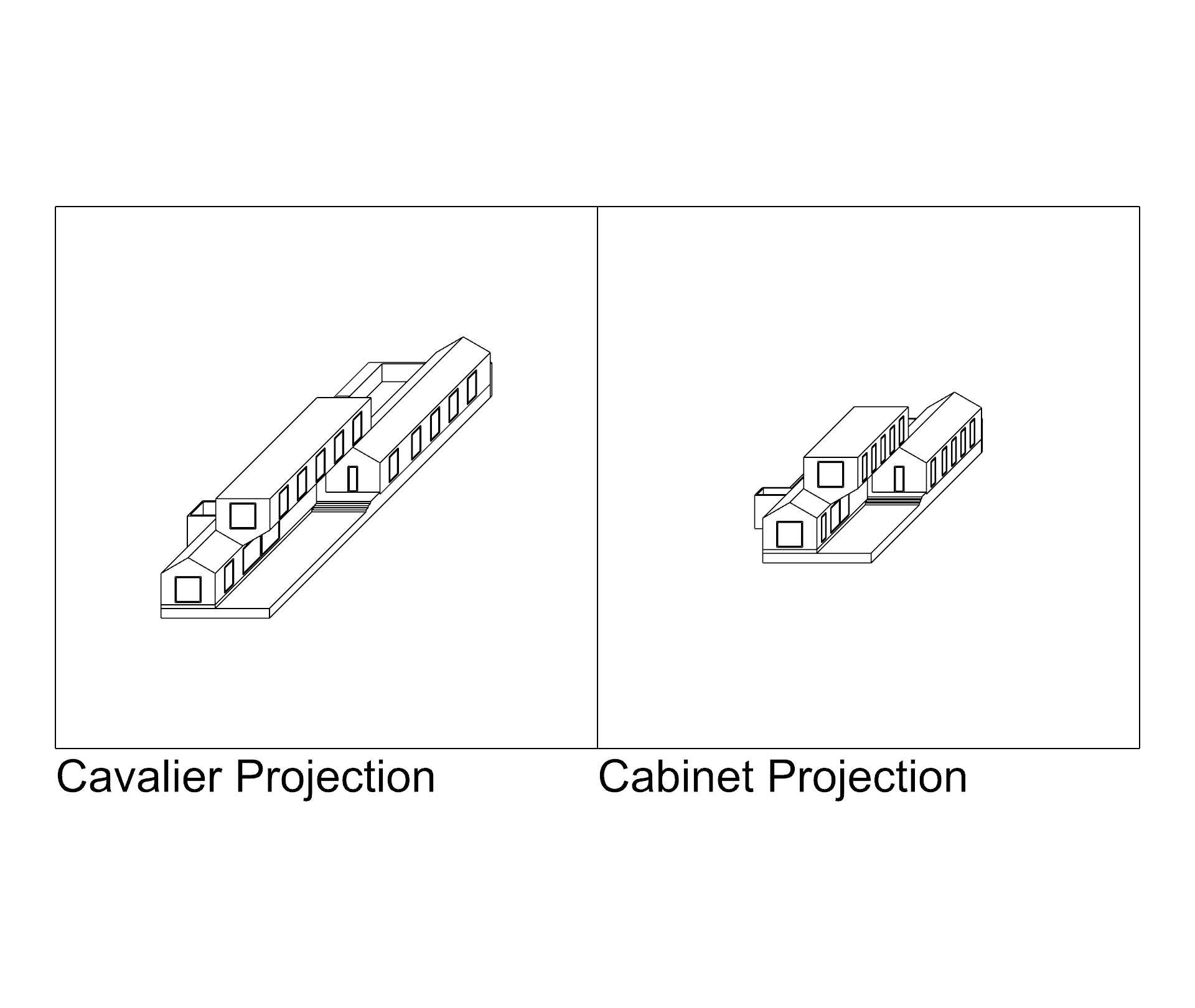
There are other types of oblique projection that depict elevation accurately, rather than plan. These are less common in architectural representation, but see if you can recreate them using the tools introduced above.
Cavalier Projection: Similar to a 45 plan oblique, but an elevation is preserved rather than the plan. Lines "receding" from the viewer are the correct length, but angles and diagonal distances are distorted.
Cabinet Projection: Cavalier projection can appear "stretched" because we expect planes receding from our view to be foreshortened. Cabinet projection corrects for this by compressing those planes: lines along the Y-axis will be half as long in the drawing as the are in reality.
Conclusion
In this tutorial we learned about different ways of projecting three-dimensional geometry onto a two-dimensional picture plane, but we did so using only line geometry. Next time we'll cover simple materials, lighting and rendering.

